
Solenoid Valve - How They Work
A solenoid valve is an electrically controlled valve. The valve features a solenoid, which is an electric coil with a movable ferromagnetic core (plunger) in its center. In the rest position, the plunger closes off a small orifice. An electric current through the coil creates a magnetic field. The magnetic field exerts an upwards force on the plunger opening the orifice. This is the basic principle that is used to open and close solenoid valves.
Quick solenoid valve notes :
- Only used for clean liquids and gases.
- Indirect operated valves require a pressure differential to function.
- Are used to close, open, dose, distribute, or mix the media with 2 or more inlets/outlets.
- Options for manual overrides, ATEX, gas approval, media separation and more.
- Can get hot as it requires energy to switch and stay in that position (depending on type).
- Common in heating systems, compressed air, vacuum, irrigation, car washes, etc.
- Fast acting.
Ready to buy a solenoid valve? View our online selection by clicking a category below!

Pilot Operated Diaphragm Valve (NC)

Pilot Operated Diaphragm Valve (NO)

Semi Lift Diaphragm Operated Solenoid Valve Normally Closed
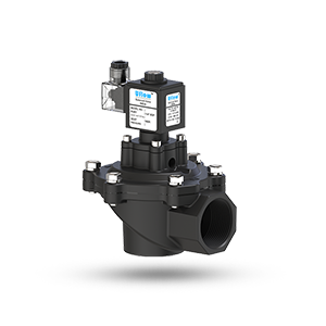
Pulse Jet Angle Type Dust Collector Valve

Pilot Operated Piston Type Steam Valve (NC/NO)

Semi Lift Diaphragm Operated Solenoid Valve Normally Open
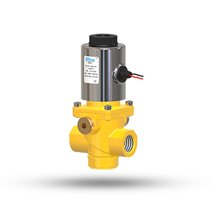
Gas Solenoid Valve

Pilot Operated Diaphragm Type Solenoid Valve (NC)

2/2 Way Direct Acting Valve (NC/NO)

3/2 Way Direct Acting Valve (NC)
Table of Contents
- How does a solenoid valve work?
- Circuit functions of solenoid valves
- Solenoid valve types
- Solenoid valve working principles
- Selection criteria
- Solenoid valve applications
- FAQ
How does a solenoid valve work?
A solenoid valve consists of two main components: a solenoid and a valve body (G). Figure 2 shows the components. A solenoid has an electromagnetically inductive coil (A) around an iron core at the center called the plunger (E). At rest, it can be normally open (NO) or normally closed (NC). In the de-energized state, a normally open valve is open and a normally closed valve is closed. When current flows through the solenoid, the coil is energized and creates a magnetic field. This creates a magnetic attraction with the plunger, moving it and overcoming the spring (D) force. If the valve is normally closed, the plunger is lifted so that the seal (F) opens the orifice and allows the flow of the media through the valve. If the valve is normally open, the plunger moves downward so that the seal (F) blocks the orifice and stops the flow of the media through the valve. The shading ring (C) prevents vibration and humming in AC coils.
Solenoid valves are used in a wide range of applications, with high or low pressures and small or large flow rates. These solenoid valves use different operating principles that are optimal for the application. The three most important ones are explained in this article: direct acting, indirect acting, and semi-direct acting operation.

Circuit functions of solenoid valves
Solenoid valves are used to close, open, dose, distribute or mix the flow of gas or liquid in a pipe. The specific purpose of a solenoid valve is expressed by its circuit function. An overview of 2-way and 3-way solenoid valves is below. For an in-depth understanding of symbols and understanding circuit function diagrams, view our valve symbol page.
2-way solenoid valve
A 2-way solenoid valve has two ports, an inlet and an outlet. Flow direction is critical to ensure proper operation, so there is typically an arrow indicating the flow direction. A 2-way valve is used to open or close the orifice. Figure 3 shows an example of a 2-way solenoid valve.
Figure 3: 2-way solenoid valve
3-way solenoid valve
A 3-way valve has three connection ports. Typically, it has 2 states (positions) it can be in. So, it switches between two different circuits. A 3-way valve is used to open, close, distribute, or mix media. Figure 4 shows an example of a 3-way solenoid valve.
Figure 4: 3-way solenoid valve
Solenoid valve types
Normally closed solenoid valve
For a normally closed solenoid valve, the valve is closed when de-energized and the media cannot flow through it. When current is sent to the coil, it creates an electromagnetic field that forces the plunger upwards overcoming the spring force. This unseats the seal and opens the orifice allowing the media the flow through the valve. Figure 5 shows the operating principle of a normally closed solenoid valve in the de-energized and energized states.

Figure 5: Operating principle of normally closed solenoid valve: de-energized (left) & energized (right)
Normally open solenoid valve
For a normally open solenoid valve, the valve is open when de-energized and the media can flow through it. When current is sent to the coil, it creates an electromagnetic field that forces the plunger downwards overcoming the spring force. The seal is then seating in the orifice and closing it, which prevents media from flowing through the valve. Figure 6 shows the operating principle of a normally open solenoid valve in the de-energized and energized states. A normally open solenoid valve is ideal for applications that require the valve to be open for long periods of time as this is then more energy efficient.

Figure 6: Operating principle of normally open solenoid valve: de-energized (left) & energized (right)
Bi-stable solenoid valve
A bi-stable or latching solenoid valve can be switched by a momentary power supply. It will then stay in that position with no power. Therefore, it is not normally open or normally closed as it stays in the current position when no power is applied. They accomplish this by using permanent magnets, rather than a spring.
Solenoid valve working principles
Direct acting
Direct acting (direct operated) solenoid valves have a simple working principle, which can be seen in Figure 7 along with the components. For a normally closed valve, with no power the plunger (E) blocks the orifice with the valve seal (F). A spring (D) is forcing this closure. When power is applied to the coil (A), it creates an electromagnetic field, attracting the plunger up, overcoming the spring force. This opens the orifice and allows the media to flow through. A normally open valve has the same components, but works in the opposite way.
The maximum operating pressure and flow rate are directly related to the orifice diameter and the magnetic force of the solenoid valve. Therefore, a direct acting solenoid valve is typically used for relatively small flow rates. Direct operated solenoid valves require no minimum operating pressure or pressure difference, so they can be used from 0 bar up to the maximum allowable pressure.

Figure 7: Direct acting solenoid valve working principle and components: coil (A); armature (B); shading ring (C); spring (D); plunger (E); seal (F); valve body (G)
Indirect acting (servo or pilot operated)
Indirect acting solenoid valves (also called servo operated or pilot operated) use the pressure differential of the medium over the valve inlet and outlet ports to open and close the valve. Therefore, they typically require a minimum pressure differential of around 0.5 bar. The working principle of an indirect acting solenoid valve can be seen in Figure 8.
The inlet and outlet ports are separated by a rubber membrane, also called diaphragm. The membrane has a small hole so that the medium can flow to the upper compartment from the inlet. For a normally closed indirect acting solenoid valve, the inlet pressure (above the membrane) and supporting spring above the membrane will ensure that the valve remains closed. The chamber above the membrane is connected by a small channel to the low-pressure port. This connection is blocked in the closed position by the plunger and valve seal. The diameter of this "pilot" orifice is larger than the diameter of the hole in the membrane. When the solenoid is energized, the pilot orifice is opened, which causes the pressure above the membrane to drop. Because of the pressure difference on both sides of the membrane, the membrane will be lifted and the medium can flow from inlet port to outlet port. A normally open valve has the same components, but works in the opposite way.
The extra pressure chamber above the membrane acts like an amplifier, so a small solenoid can still control a large flow rate. Indirect solenoid valves are only used for media flow in one direction. Indirect operated solenoid valves are used in applications with a sufficient pressure differential and a high desired flow rate.

Figure 8: Indirect acting solenoid valve working principle